This is a semi-automatic printable SMD feeder for both manual and automatic pick-and-place (PnP) machines. It uses the mechanical energy from a lever depressed by the user or picking head to both advance the carrier tape, and to peel off and take-up the cover tape.
The design is based off one by Dining-Philosopher, which was inspired by Alexavr2 and Karl Ekdahl. Like the earlier designs, this version was designed for manufacture. Components are kept small enough to permit the use of smaller 3D printers (190 mm x 190 mm minimum bed size) and later screwed together.
Tape Advancement
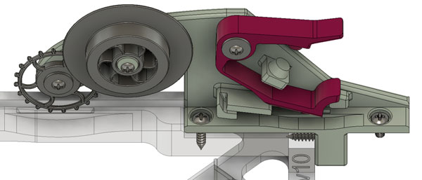
When the feed lever is depressed (magenta part in image above), it pulls back a small tooth that ratchets over the carrier tape’s feeder holes. When the lever is then released, this tooth fits into the next feeder holes and advances the tape (4 mm advance, assuming standard 8 mm wide carrier tape). This method ensures reliable and accurate tape advancement that is independent of exactly how far the lever is depressed.
Cover Tape Take-Up
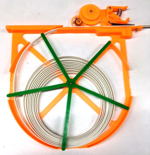
The SMD components are kept in the carrier tape pockets by a thin film of plastic or paper. I initially tried a design (see below) that pulled the tape back in segments, exposing multiple components at a time. But I found that the act of picking up one component would often vibrate the tape enough to dislodge and disorient the other exposed components. For a manual PnP system this was frustrating and time consuming, for an automatic PnP system this is unusable.
Dining-Philosopher’s solution to cover tape take-up were carefully selected weights that provided enough tension to remove the cover tape but not pull the carrier tape forward. This is a viable option, but it requires lots of space and periodic maintenance of moving the weights back up after they have descend with use.
The method used with this design is loosely based on the low-cost Chinese PnP machines that use a rotating bar to take-up the cover tape. Each feeder on those systems has a small winding spool that is connected to the rotating bar with a slip joint that has adjustable tension. Tension is then adjusted until the rotating bar provides enough tension to remove the cover tape but not pull the carrier tape forward. But instead of relying on an externally powered rotating bar, this design uses some of the stored energy in the depressed feed lever to also rotate the winding spool.

The cover tape winding spool is slightly over-geared (10:9) so it will take up any slack that forms. The ‘secret sauce’ is a slip connection between its power gear and the spool itself. Tension adjustment is either accomplished by slightly reaming the winding spool’s axial hole larger or by printing a new winding spool with a larger axial hole. While this is not ideal, it did keep the design narrow and simple.
Gear 2 was designed with flex in the contact surfaces to help ensure constant tension, even with varying print quality and plastic types. With a light application of a dry lubricant (I used molybdenum disulfide powder since I have a large quantity on-hand), this has been proven to work with PLA, ABS, and PETG prints.
Reel Holder
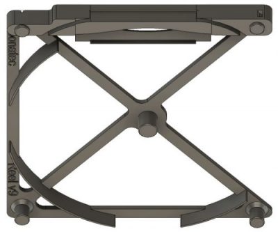
The other major change that I made was to incorporate a simple reel holder. Like commercial feeders, this permits easy and quick feeder changing. Because I also order cut-tape quantities of some parts, I designed the reel holder to work for those as well. To do this, there is a mostly complete outer wall and large ‘fingered washer’ (green part in image below) to hold the partial lengths of cut-tape in place.
To add a new reel into the feeder, the reel is first placed in its holder and secured by a plastic washer. If a cut-tape is used instead, then it is secured in the holder with a larger ‘fingered washer’ to keep it in place. Then the carrier tape and cover tape are threaded through the feeder mechanism. Finally the cover-tape is pulled back and attached to the winding spool with narrow tape.
Finally, the whole assembly is designed to slide into a 20 mm x 20 mm aluminum extrusion frame. The front of the feeder was modified to permit a screw (#M3 or #4) to go into drop-in nut, to allow it to be quickly secured in place.
Assembly
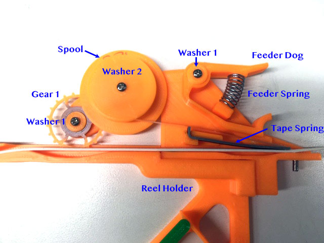
Parts to Print
- 1x Feeder
- 1x Feeder Dog
- 1x Tape Spring – because I didn’t want to wait for the metal one to ship…
- 1x Reel Holder
- 1x Gear 1
- 1x Gear 2
- 2x Washer 1 – for Feeder Dog and Gear 1
- 1x Washer 2 – for Spool
- 1x Washer 3 – for holding Reel instead of Washer CT
- 1x Washer CT – for holding cut-tape instead of Washer 1
- 1x Spool – pick appropriate size for needed tension
- 1x Drop-in T-Nut for 2020 – #4 size, M3 size
Parts to Purchase
- 1x Feed Lever Coil Spring – I use a 2.5 lb, 1″ x 0.3″ compression spring
- 1x Feed Tooth – I use a 1/16″ steel dowel pin, can also use 1/16″ brass rod (cut to size)
- 2x #4 Screws – 5/16″ long
- 4x #2 Screws – 1/4″ long
- 1x Metal nut for Drop-in T-Nut for 2020 – #4-40 size
- 1x Screw for Drop-in T-Nut – #4 1/4″ size
Tools that will make assembly easier
- 23/32″-25/32″ Adjustable-Size Reamer – for cleaning up and slightly adjusting the Winding Spools axial hole
- 1/4″-9/32″ Adjustable-Size Reamer or 1/4″ Drill Bit – for cleaning up the mounting hole on Gear 1 and the Feeder Dog
- Phillips screwdriver – Yes, you could use pliers to put the screws in, but why do everything the hard way?
- Dry Lubricant – It will help reduce the stiction between Gear 2 and the Winding Spool, ensuring a more constant cover tape removal tension. Graphite from a pencil, moly powder, teflon powder, etc.
Assembly Steps
- Print out and purchase all parts mentioned above
- Clean and smooth printed parts with adjustable reamers (or drill bits) and sandpaper
- Slightly warm and press 1/16″ Dowel into bottom of Feeder Dog (hole in print)
- Should stick out about 1/8″ (3 mm)
- Screw Feeder onto Reel Holder with 2x #4 screws
- Apply dry lubricant to Gear 1 and Gear 2’s center axial hole (where it pivots)
- Place Gear 1, center step facing away from Feeder
- Attach with Washer 1 and a #2 screw
- Make sure outer teeth are in grove in Reel Holder
- Slide Spool onto Gear 2 and check friction
- Place onto Feeder, attach with Washer 2 and a #2 screw
- Ensure Gear 1 and Gear 2 mesh properly
- Put Feeder Dog onto Feeder, attach with Washer 2 and a #2 screw
- Slide Tape Spring into Feeder
- Put #4 screw (pictured) and Drop-In T-Nut (not pictured) on Feeder
Loading Steps
- Place SMD reel into Reel Holder, attach with Washer 3 and #2 screw
- Or place cut-tape into Reel Holder, attach with Washer CT and #2 screw
- Feed end of carrier tape under Gear 1, Tape Spring, and Feeder Dog’s Dowel
- Lift cover tape and feed back to Spool by going over Tape Spring. Attach with narrow tape, winding clock-wise (goes onto spool on the bottom)
- Ensure Dowel rides on top of carrier tape
- Depress Feeder Dog’s lever a couple of times to ensure carrier tape is feeding correctly and to take up any slack in the cover tape
This feeder has been released as an Open Source Hardware Project. For more information, please see: https://bitbucket.org/Loonatec/pnp_semi-automatic_feeder/
Note: Initial CAD work was performed in Autodesk’s Fusion 360. However, after having extensive licensing trouble with my Fusion 360 Start-up license (month+, finally resolved), I switched to FreeCAD.
Welcome.
A very good solution.
I printed one set for trial.
IT WORKS !!!.
However, it does not fit my machine. I have to do the fixing differently, move the tape space a little.
Would you share FreeCad files with me?
It would save me some work.
Regards.
Krzysztof
Krzysztof,
See the latest design on the Bitbucket repository. I’ve moved the design back to FreeCAD after Autodesk recently changed the Fusion360 licensing options again. The model now is now also partially parametric.
Mate, appreciate the effort you’ve put in, I really like the simplicity of the design and lack of additional configuration on the PNP side of things… Will be printing some of these out with the new printer. Appreciate it!
Hi Jed, I am really impressed by this design. I would like to test it, but I am a little lost. It seems that the guide you provide was not updated for the latest design. I am also not used to FreeCAD (yet!).
1. Could you please provide an updated parts list and picture of the new assembled feeder?
2. My first printed version is way too tight. How can I find the “Printer Fudge Factor” that is mentioned in the Readme?